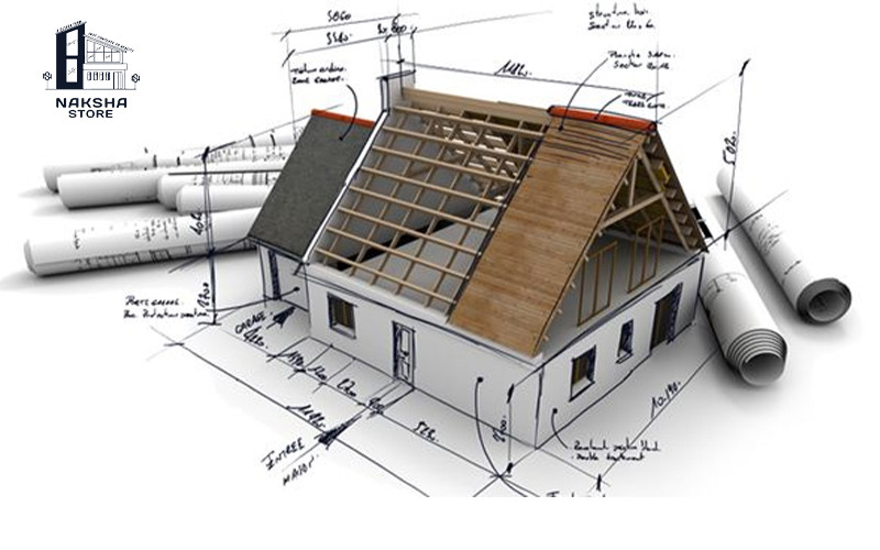
Working drawings, also known as construction drawings or blueprints, are detailed technical drawings that provide instructions and information for the construction or implementation of a building or structure. These drawings are typically created by architects, engineers, and other design professionals and serve as a communication tool between the design team and the contractors or builders. Here are the key components and types of working drawings:
Architectural Drawings:
Floor Plans: Provide a top-down view of each floor, showing the layout, dimensions, and relationships between rooms, walls, doors, and windows.
Elevation Drawings: Show the exterior views of the building, illustrating the vertical dimensions, proportions, and architectural details of each façade.
Section Drawings: Represent vertical or horizontal cuts through the building to showcase the internal structure, heights, and relationships between different spaces.
Detail Drawings: Provide close-up views and specific instructions for the construction of complex architectural elements or details, such as staircases, windows, or moldings.
Structural Drawings:
Foundation Plans: Show the layout and dimensions of the building's foundation, including footings, walls, and other structural elements that support the building's load.
Framing Plans: Illustrate the arrangement and dimensions of structural components, such as beams, columns, walls, and floor/roof systems.
Reinforcement Details: Specify the size, spacing, and placement of reinforcement bars in reinforced concrete elements, ensuring structural integrity.
Connection Details: Provide instructions and drawings for the connections between structural elements to ensure proper load transfer and stability.
Electrical Drawings:
Power and Lighting Plans: Show the location and type of electrical outlets, switches, fixtures, and equipment, as well as the routing of electrical wiring and cables.
Panel Schedules: Provide details about the electrical panels, including the circuit breakers, loads, and connections within the electrical distribution system.
Wiring Diagrams: Illustrate the connections and pathways of electrical circuits, helping electricians understand the electrical system's layout.
Plumbing and Mechanical Drawings:
Plumbing Plans: Indicate the location and size of plumbing fixtures, pipes, drains, vents, and other components within the plumbing system.
HVAC (Heating, Ventilation, and Air Conditioning) Drawings: Show the layout of ductwork, air registers, mechanical equipment, and control systems for heating, cooling, and ventilation.
Fire Protection Drawings: Provide details on the location, type, and installation requirements of fire suppression systems, including sprinklers, fire alarms, and emergency exits.
Working drawings also include specifications, notes, and schedules that provide additional information regarding materials, construction techniques, finishes, and other relevant details. These drawings are crucial for contractors to accurately interpret and execute the design intent, ensuring that the construction process aligns with the project's requirements and standards.